



Welcome to E.E.L.D.A.R.
Electrical Engineering Laboratories for Design, Advanced Studies, and Research.
Any computer weenie can hack IN.
It takes an EELDAR to get OUT.
Here at the labs, we have a couple pilots.
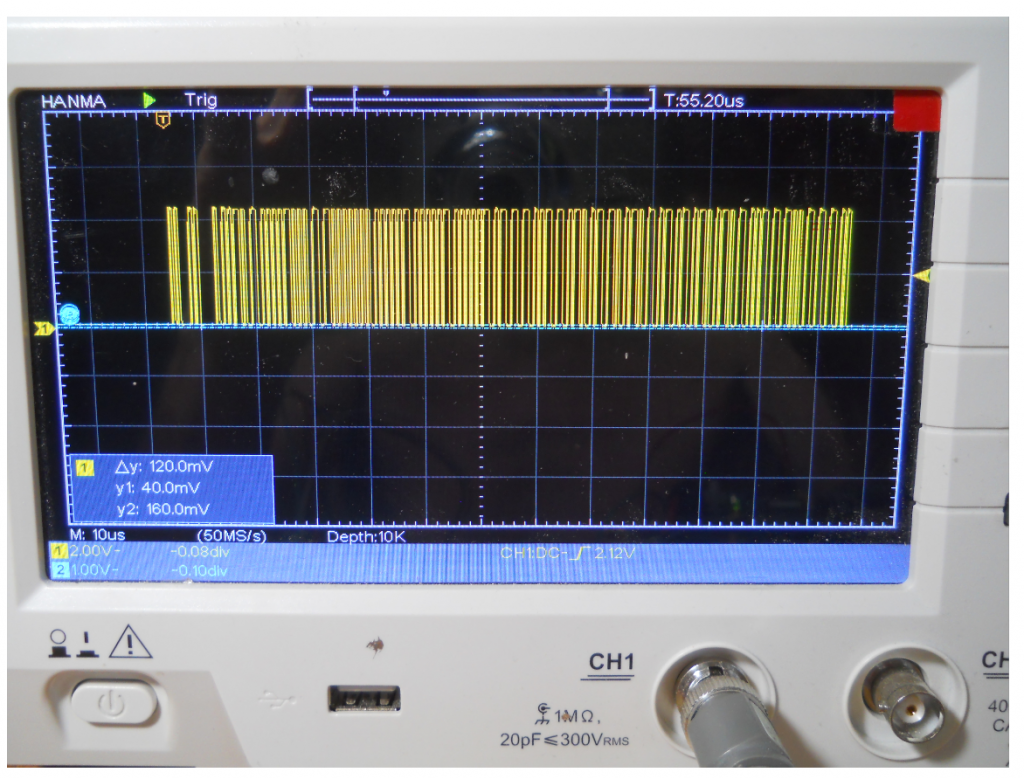
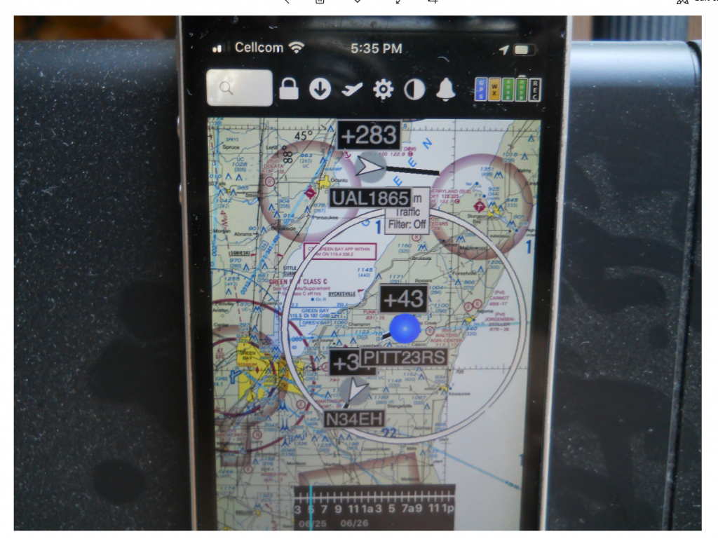
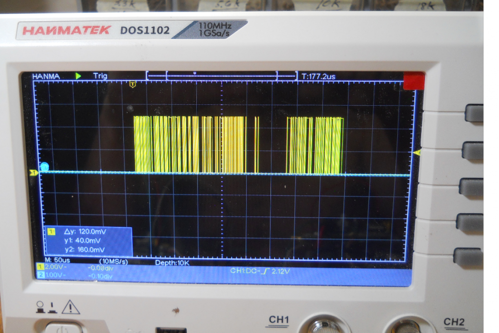
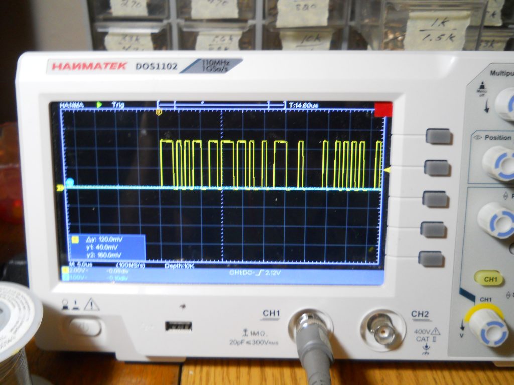
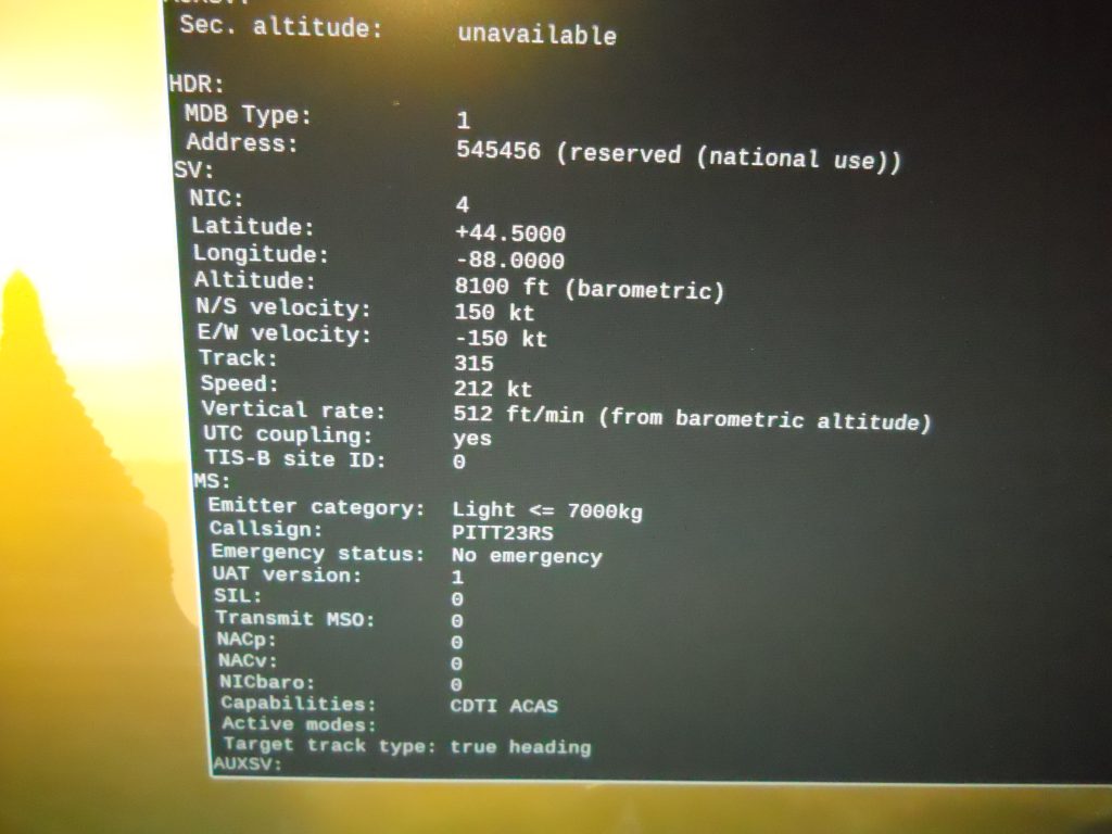
ADS-B is part of the new FAA push to NextGen and we decided to look into the details and share them with the pilot that has a dash of engineer. Wants to know more than simply what it costs like fat cat rich guys. That is the motivation for this effort. The owner can assemble a simple circuit board on the bench, then take a look at real time ads-b out signals on an oscilloscope and/or logic analyzer (see slides below). And watch it all happen.
We could write a program with a cool gui that spits out all the hex code and illustrates the fields, but that’s for the weenie. We prefer the soldering up a board hands on approach.
There are four parts to this process:
1) Parsing the gps serial data for positional and velocity information. There is much other information to be transmitted such as barometric altitude, aircraft weight, performance, and other capabilities, but that’s not the point here. This is all intended to be a learning tool.
2) Post Processing – some math (CPR stuff and breaking velocities into vector components).
3) Formatting – Arranging the data into specified ES1090 frame fields and UAT978 message fields. Pulse Position Modulating the ES1090 frames and complimentary output for UAT978 messages.
4) Up Converting – ASK for ES1090 and CPFSK for UAT978.
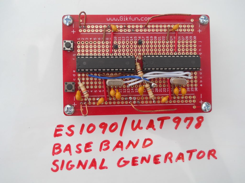
For now we are offering what we call the Base Band Gererator kits. They perform steps 1, 2, and 3 for either ES1090 or UAT 978. See kit information below.
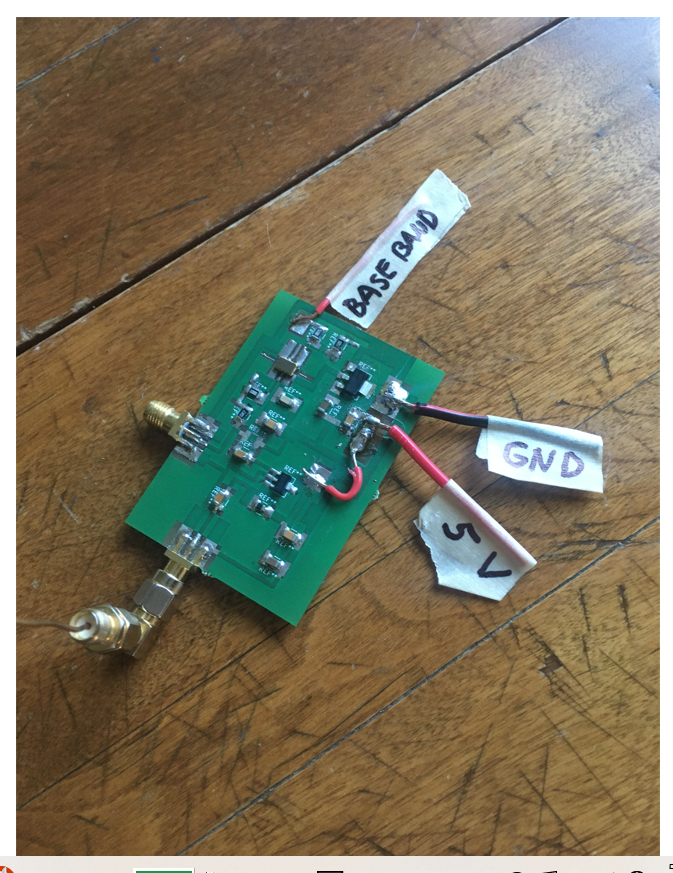
We also offer the up converters for step 4. However, they are preassembled and not kits due to RF design issues. See spec. information below.
A front end module including the up converters and PA has been designed but not available for use with these kits.
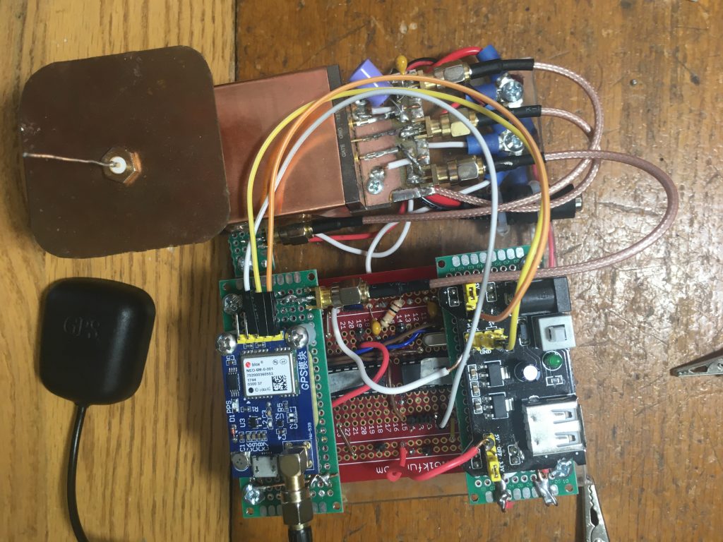
A Base Band kit, up converter, gps module and antenna, and a12 volt source would constitute a complete ads-b OUT transmitter. Real time position and velocity information will show up on an ads-b IN display if the transmitter is near enough.
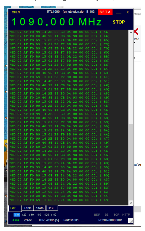
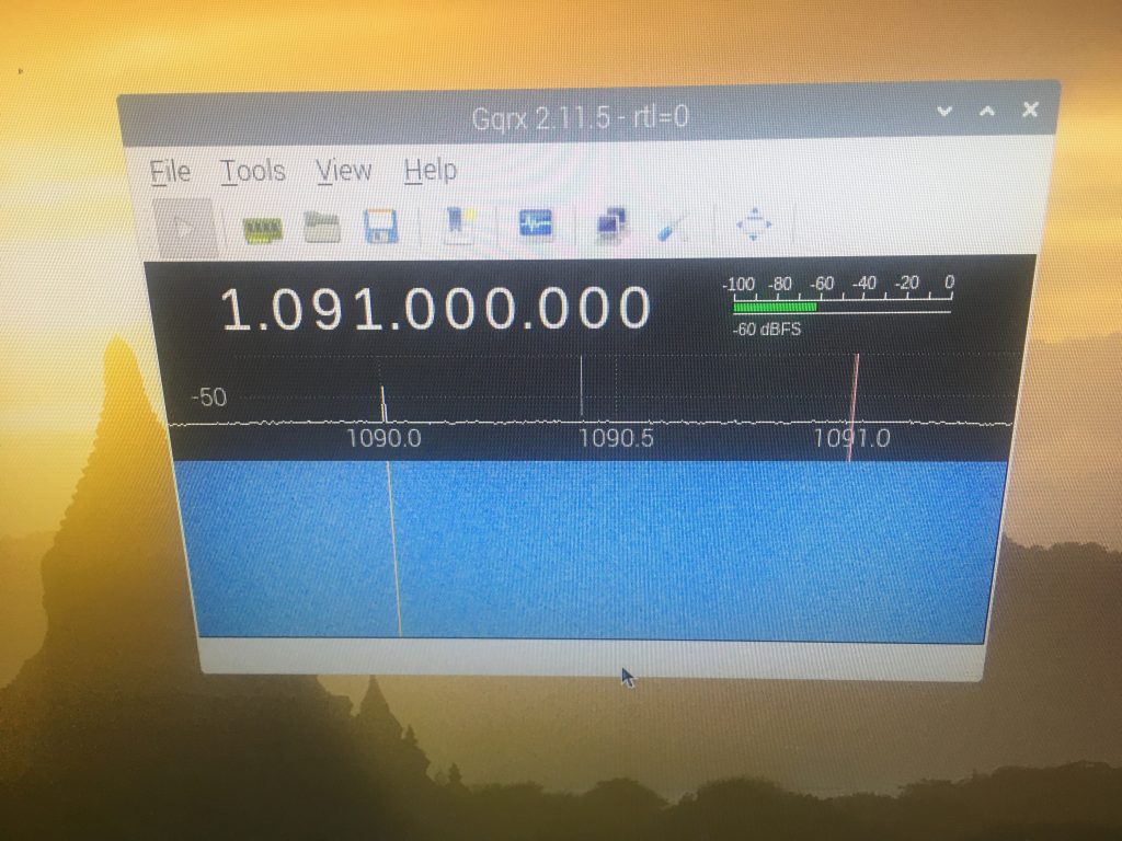
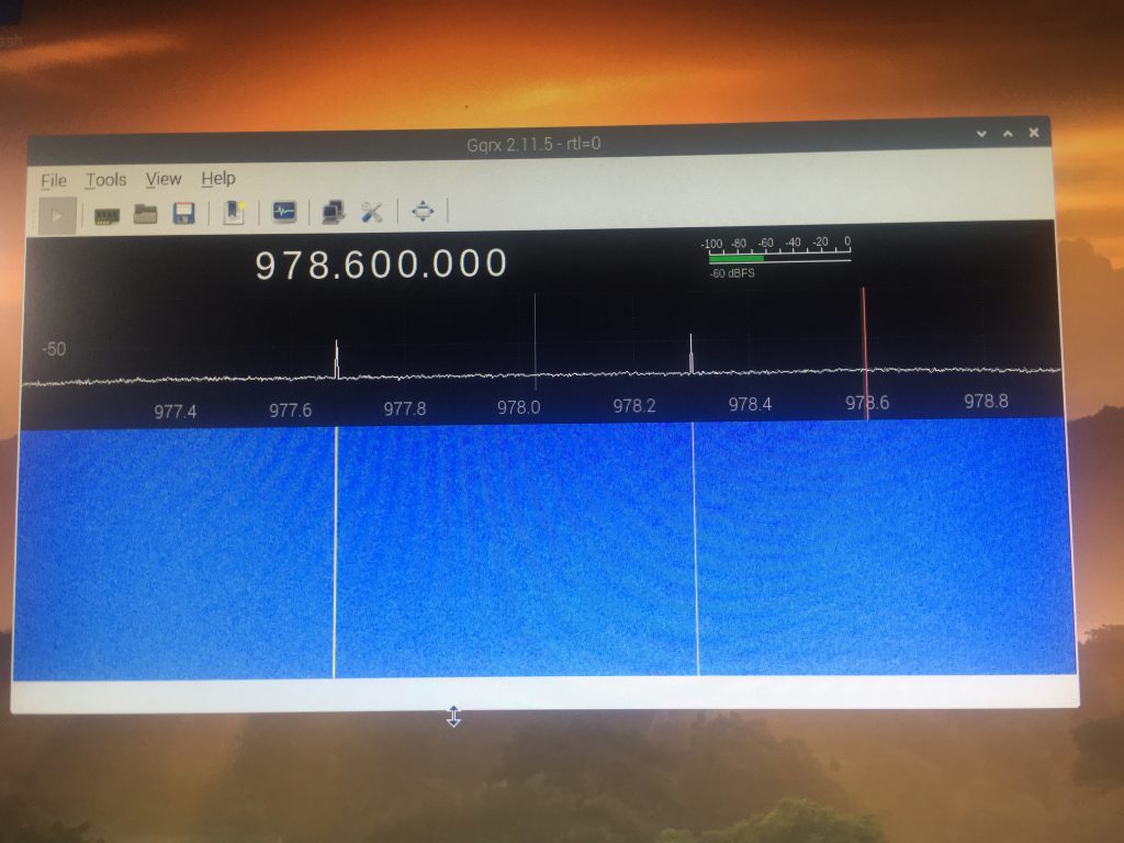
With this, an SDR, and open source software like Dump1090, Dump978, or RTL1090, you can drive around or fly anound and watch the position, altitude, speed, and heading numbers change in real time on your laptop. Great learning project.
We are also looking for a software guy to port all this code over to an ARM micro. When that is complete, the ARM, together with the front end module, should constitute the world’s tiniest and lightest ads-b out transmitter. Simply bragging rights for E.E.L.D.A.R. See project manager below.
**** IMPORTANT ****
None of this information, hardware, or software is certified or approved by the FAA for use in any aspect of general aviation. The up converters are micro power. Not effective beyond short range testing distances. It is strictly a hobby type project to learn more about ADS-B OUT.

Come join the EELDAR teem. Exceptional benefits.
ADS-B OUT ES1090/UAT978 Base Band Signal Generator Kits
These products are kits to be assembled by the owner. It’s function is to output real time ADS-B Out Airborne Position, Airborne Velocity, and Aircraft Identification baseband signals.
The Circuit requires 5 Volt power.
INPUT – ES1090/UAT978
$GPRMC and $GPGGA NMEA sentances from a 3.3V/5V GPS module serial TX output programmed to 9600 baud.
OUTPUT – ES1090
Airborne Position: CPR(even) and CPR(odd) latitude and longitude, and altitude(ft).
Airborne Velocity: East/West velocity sign. East/West velocity(kts.) North/South velocity sign. North/South velocity(kts.)
Aircraft Identification: Frame is arbitrarily set to PITT23RS. Can be modified by special request.
ONLY the above fields are updated via GPS. All other fields are arbitrary.
All frames include 8 preamble bits and 24 CRC error detection bits.
All data is Pulse Position Modulated and ready for up conversion to 1090Mhz carrier frequency. Data bit period = 1.0uS.
Frames are updated every 2 seconds continuously.
OUTPUT – UAT978
Airborne Position: latitude, longitude, and altitude(ft).
Airborne Velocity: East/West velocity sign. East/West velocity(kts).
North/South velocity sign. North/South velocity(kts).
Aircraft Identification: Call sign is arbitrarily set to PITT23RS. Can be modified by special request.
ONLY the above fields are updated via GPS. All other fields are arbitrary.
All messages include 36 bit sync sequence and 14 reed-solomon ECC symbols.
Complementary output. All data is ready for up conversion to 978Mhz + 312.5Khz (binary 1 – ‘mark’) and 978Mhz – 312.5Khz (binary 0 – ‘space’) carrier frequencies. Data bit period = 0.96us. Modulation must be CPFSK (Continuous Phase Frequency Shift Keying).
Frames are updated every 2 seconds continuously.
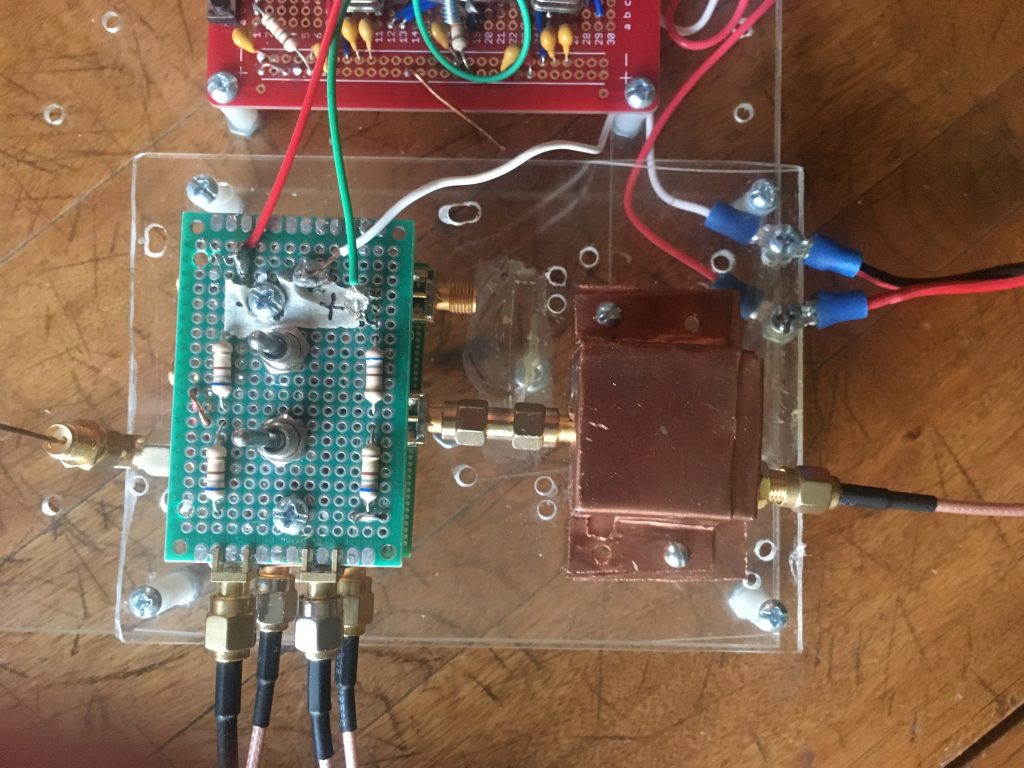
Kit is for baseband gererator only. GPS module and Up Converter not included. Kit includes close up photo, schematics, instructions, proto board, pre-programmed ICs, crystals, switches, and all passive components.
Up Converter Units
These assembled circuit boards modulate the carrier frequencies with the digital base band information.
ES1090
INPUT – Pulse Position modulated ES1090 binary frame data at 1 Mbit rate. 3.3V supply.
OUTPUT – 1090 Mhz pulsed RF. 9.9dBm antenna power. ASK.
UAT978
INPUT – Binary UAT978 message data at 1.04166 Mbit rate. 3.3V/5.0V supply.
OUTPUT – Pulsed RF. (978Mhz + 312.5Khz) for binary One. (978Mhz – 312.5Khz) for binary Zero. 9.9dBm antenna power. CPFSK.
Boards include schematics, instructions, and photo for hookup to base band kit and gps modules.
Contact information – adsbexp@ads-b-out-diy-kit.com

Experimental ADS-B OUT Transmitter


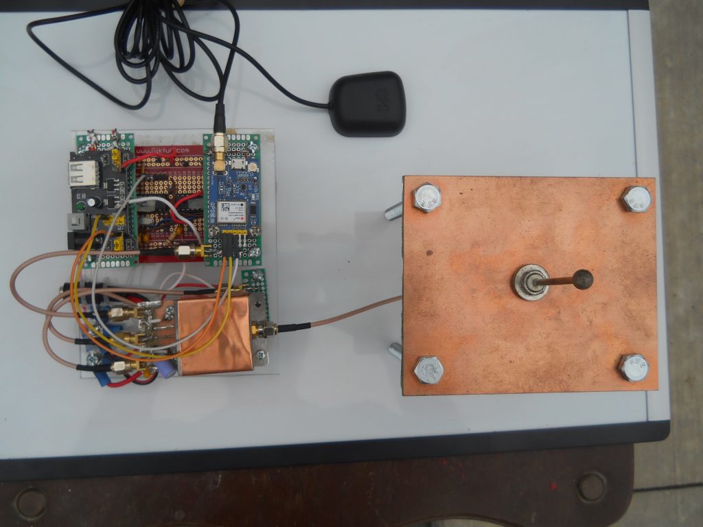
WILL SELL
Working ES1090 or UAT978 prototype ads-b OUT transmitters. Includes all drawings, schematics, photos, well documented software, a thorough presentation, and assistance with what your intentions are.
MAKE AN OFFER
Contact information – adsbexp@ads-b-out-diy-kit.com